To build a remote control for a drone, you'll need a microcontroller like Arduino and a wireless communication module like NRF24L01.
The NRF24L01 module is a popular choice for wireless communication due to its low power consumption and high data transfer rate of up to 2 Mbps.
You'll also need to connect the NRF24L01 module to the Arduino board and write code to transmit and receive data.
The Arduino code will be written in C++ and will use the NRF24L01 library to handle communication between the Arduino and the drone's receiver.
See what others are reading: Drone Remote Id Broadcast Module
Hardware Setup
To set up the hardware for your drone's remote control, you'll need to start with the receiver. The materials required are the NRF24L01 module, Arduino UNO, wires, and a Breadboard/Zero PCB. The setup is similar to the transmitter's setup, so it's a breeze.
You'll need to follow the steps outlined in the previous setup to connect the components. This will complete the hardware setup of your drone receiver.
For the remote controller's hardware and electronics, you can choose components based on the type of project or robot you're trying to control. For example, a simple robotic tank might only require four push buttons to move forward and backward, turn left and right.
Here are some key components to consider for your remote controller:
- Toggle Switch x 4
- 2-Axis Joystick x 2
- Potentio Meter x 4
- Push Button x 6
- LED x 3
- LCD x 1
- Arduino Mega x 1
- Cables x many
- Small Breadboard x 2
- Ciesco XRF Wireless Modules x 2
The Arduino Mega was chosen for its abundance of analogue and digital pins, which the UNO lacks. This will give you more flexibility in designing your remote controller's electronics.
Drone and Remote Connection
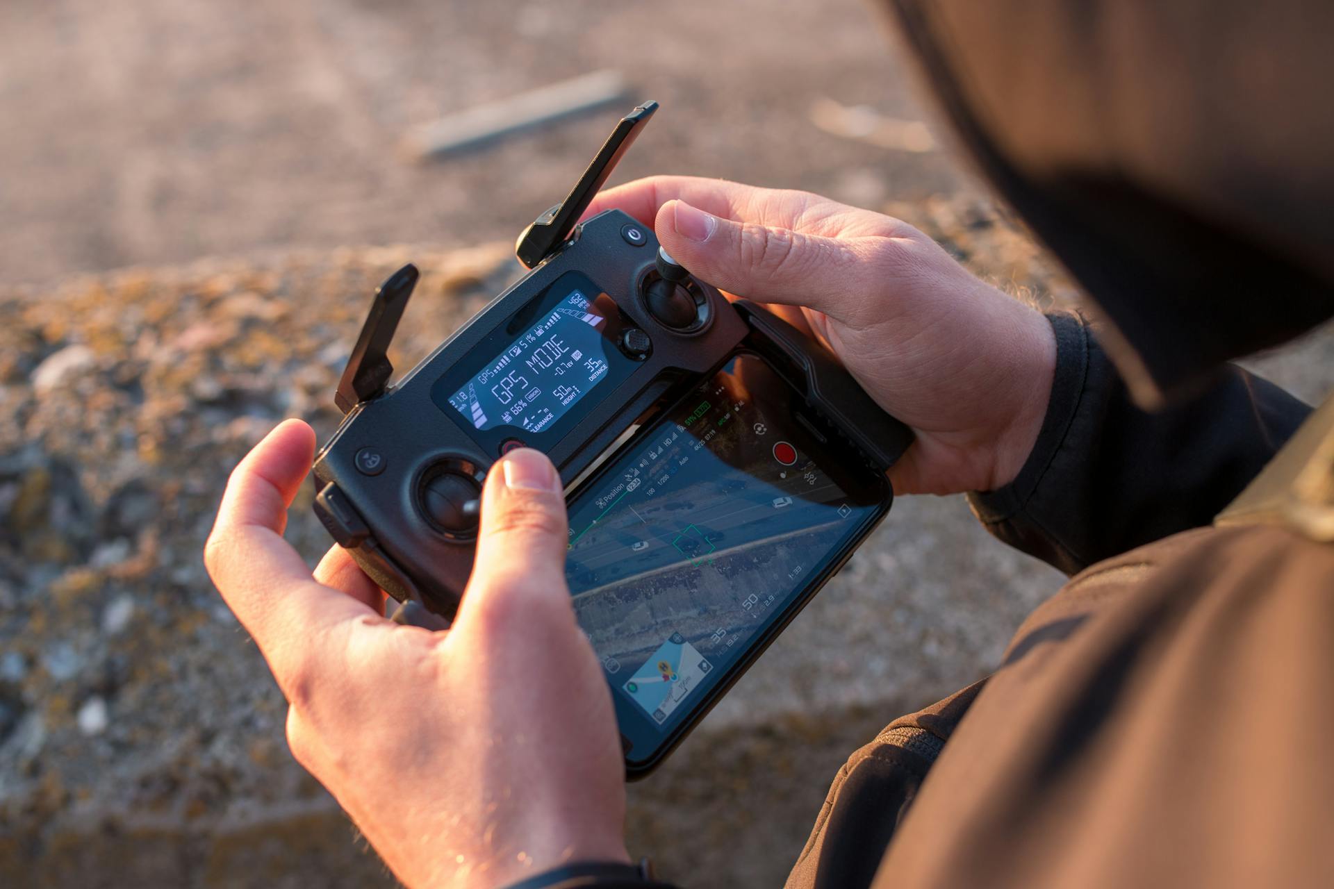
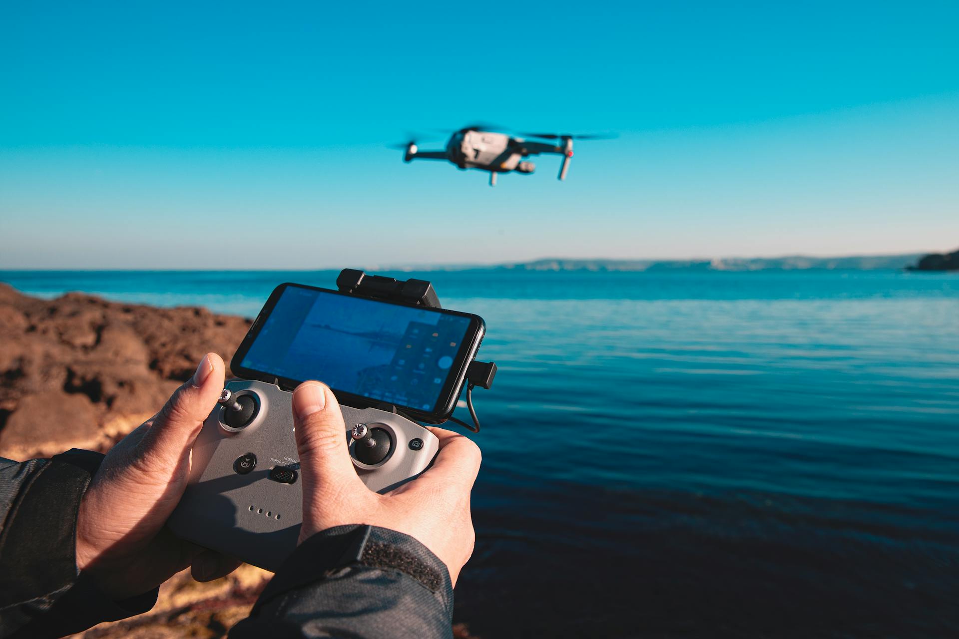
Drones are controlled remotely by a handheld transmitter that communicates with the drone's receiver via radio frequency (RF) signals. This allows for real-time control and feedback.
The transmitter typically has joysticks or other controls to command the drone's movements, and it may also feature a video display for viewing the camera feed from the drone. This is a crucial part of the remote connection.
To establish a connection, the transmitter sends RF signals to the receiver, which then decodes the signals and sends them to the drone's flight controller. This process enables the drone to respond to the transmitter's commands.
The NRF24L01 module is used in the drone receiver setup, along with an Arduino UNO, wires, and a breadboard or zero PCB. This setup is similar to the transmitter setup, but with a focus on receiving and decoding RF signals.
Here are the key components involved in the remote connection:
- NRF24L01 module
- Arduino UNO
- Wires
- Breadboard or zero PCB
- Transmitter
- Receiver
- Flight controller
NRF24L01 Transceiver Module
The NRF24L01 Transceiver Module is a crucial component in setting up a drone's remote connection.
The NRF24L01 module is required for the setup of our drone Receiver, as mentioned in the previous step.
We need to connect the NRF24L01 module to the Arduino UNO, wires, and Breadboard/Zero PCB for the setup.
The setup process is similar to the one done in the previous step, which was the Drone Transmitter setup.
A fresh viewpoint: Faa Drone Remote Id Module
To complete the Hardware setup of our Drone Receiver, we just need to upload the code after the setup is done.
Before uploading the final code, we will upload a test code on the Arduino UNO to display the values received by the Receiver on the Serial Monitor of the Arduino IDE.
This test code will help us ensure that the Receiver is working correctly before moving on to the final code upload.
Completing the Pair
The final step in setting up your drone's receiver is to test the pair and ensure it's working correctly. This involves uploading a test code to the Arduino UNO.
You'll need to head over to the Github repository and download the "Receiver_test" file, which is specifically designed for testing the performance of your transmitter-receiver pair.
To upload the test code, connect your receiver circuit to your PC, select the correct board and COM port, and hit the upload button in your Arduino IDE.
Once the upload is complete, keep the receiver connected to your PC and turn on your transmitter. Open the Serial Monitor in your Arduino IDE and set the baud rate to 250000.
As you move the joysticks on your transmitter, you'll notice the Serial Monitor values change accordingly, confirming that your transmitter and receiver pair are working fine.
Now that you've confirmed the pair is working, you can upload the final code to the receiver's Arduino UNO. Simply open the "Drone_Receiver" file from the Github repository, select the correct COM port and board, and hit the upload button.
Remote Control Circuit
For the remote control circuit, you'll need a brain that can process the inputs from your control components. The Arduino Pro Mini is a great choice, as it's powered by 2 LiPo batteries producing around 7.4 volts, which is then reduced to 5V using the RAW pin's voltage regulator.
The NRF24L01 module requires 3.3V, so you'll need a voltage regulator like the HT7333 or AMS1117 to convert the voltage. This is crucial for stable radio communication.
Curious to learn more? Check out: Dji Mini 4k Drone with Remote Control
To connect everything together, you can use a custom PCB designed using EasyEDA, which will make it easier to manage the many components and wires. The PCB should have enough space for all the analog and digital pins of the Arduino Pro Mini, and consider ergonomics to make it easy to hold and use.
Here are the components you'll need for the remote control circuit:
- NRF24L01 Transceiver Module
- HT7333 or AMS1117 3.3V voltage regulator
- Potentiometer
- Toggle Switch
- Joystick
- Arduino Pro Mini
PCB Design
PCB Design is a crucial step in creating a remote control circuit. You'll need to utilize all the analog and digital pins of the Arduino Pro Mini, so consider using a custom PCB to keep things organized.
A good PCB design should prioritize ergonomics, making it easy to hold and use the controller. I designed mine to fit comfortably in two hands, with controls within finger reach.
The edges of the PCB should be rounded for safety and ease of handling. I also added 3mm holes for mounting the PCB onto something later.
When designing the PCB, consider the placement of programming pins. I placed them at the top side of the controller for easy access.
The RX and TX pins of the Arduino are often used for joystick buttons, but they need to be disconnected during uploading to prevent errors. I interrupted these lines with two pins that can be easily connected using jumper caps.
Make sure to choose the right Arduino Pro Mini version to match your PCB design, or modify the design accordingly.
Component Inputs
Component inputs are a crucial aspect of a remote control circuit, and understanding how they work can save you a lot of time and frustration.
Toggle switches and push buttons are digital inputs that return true (1) when pressed and false (0) when not pressed.
Potentiometers, on the other hand, have a maximum resistance of 10K and give a value between 0 to 1023.
2-axis joysticks are essentially two potentiometers, providing two values between 0 to 1023 for the X and Y axes.
It's a good idea to test these components before using them in your project to ensure you understand how they work.
Here's a summary of the inputs for these components:
Arduino Code and Control
To get started with the Arduino code and control, you'll need to include the necessary libraries, such as SPI and RF24 for wireless communication, and I2C for the accelerometer module.
You'll also need to define the digital inputs, variables, and the radio object and communication address.
The transmitter code stores 14 input values in a structure, with a maximum size of 32 bytes, which is the NRF24L01 buffer limit.
Each input is mapped from 0 to 1023 into byte values from 0 to 255, and sent to the receiver using the radio.write() function.
The receiver code receives the data, stores it in variables, and prints it on the serial monitor to check if the transmission works properly.
If no data is received for a period longer than 1 second, the variables are reset to their default values.
Software and Setup
To set up the drone receiver, you'll need the NRF24L01 module, Arduino UNO, wires, and a Breadboard/Zero PCB. This setup is similar to the transmitter setup.
The test code will display the values received by the receiver on the Serial Monitor of the Arduino IDE, allowing you to verify the connection before uploading the final code. This step is crucial in ensuring a smooth and error-free setup.
The software for this project consists of two parts: the remote controller (Host) and the robot (Client).
Sixfab Shield
The Sixfab Shield is a game-changer for upgrading your drone for BVLOS 4G drone control.
It simply rests on top of the Raspberry Pi and provides internet via cellular networks.
You can manage sim cards through a nice dashboard on the Sixfab Shield.
The cost of data plans averages $.10 per MB, which can vary depending on the type of data you transmit with your 4G drone.
For simple telemetry transmission to a ground control station, data transmission is minimal.
You'll pay for sim data usage through the Sixfab dashboard.
Intriguing read: Remote Control Military Drone
Software Overview
The source code for this project can be found online at https://code.google.com/p/diy-rc-remote-controlle/source/browse/.
The Host software is responsible for initializing connections, re-establishing broken connections, encoding commands, and providing feedback from the Client to the user.
It also features an LCD menu system that displays current state information, allows real-time parameter adjustment, calibration, and more.
You won't find setup and loop functions in the Client header file because it's just a header file with useful functions to utilize in the Client sketch.
You'll need to write your own Client sketch, which contains the setup and loop functions, since everyone's Client side will be used for different purposes.
The Client side library will act as an interface between the robot and the controller, accepting connections, decoding commands, and communicating back.
See what others are reading: Dji - Mini 2 Se Drone with Remote Control
Setup and Assembly
To make a remote control for a drone, you'll need to set up the drone receiver. This involves using the NRF24L01 module, Arduino UNO, wires, and a Breadboard/Zero PCB.
The setup is relatively simple and similar to the transmitter setup. You'll need to connect the NRF24L01 module, Arduino UNO, and wires to the Breadboard/Zero PCB.
Before uploading the final code to the Arduino UNO, you'll need to upload a test code first. This test code will display the values received by the receiver on the Serial Monitor of the Arduino IDE.
Setting Up
Setting up your drone system requires attention to detail and the right materials. The NRF24L01 module is a crucial component for this setup.
We'll be using an Arduino UNO, which is a popular choice for many DIY projects. The setup process is similar to the previous step.
The materials needed for this step include wires, a Breadboard/Zero PCB, and the NRF24L01 module itself. To complete the hardware setup, follow the provided steps.
Before uploading the final code, we'll upload a test code to the Arduino UNO. This test code will display the values received by the receiver on the Serial Monitor of the Arduino IDE.
Assembling the PCB
Assembling the PCB is a crucial step in bringing your project to life. You'll need to carefully follow the design and layout of your custom PCB, which in this case was created using the EasyEDA free online circuit design software.
The PCB design takes into account the ergonomics of the controller, making it easy to hold with two hands and access all controls with your fingers. The edges are rounded and 3mm holes are added for mounting the PCB later.
To assemble the PCB, you'll need to carefully place the components onto the board, following the design layout. Make sure to pay attention to the placement of the pins for programming the Arduino Pro Mini, which are located at the top side of the controller.
The RX and TX pins of the Arduino are used for the joystick buttons, but these need to be disconnected while uploading the sketch to the Arduino. This is achieved by interrupting the lines with two pins that can be connected using simple jumper caps.
The Gerber file generated from the design is then used for manufacturing the PCB.
Overview and Mission
Making a remote control for a drone requires a solid understanding of the basics.
A remote control drone is a type of unmanned aerial vehicle (UAV) that can be controlled from a distance using a remote controller.
The first step in making a remote control for a drone is to choose a suitable platform, such as an Arduino or Raspberry Pi board.
With a reliable platform in place, you can start building the necessary components, including a transmitter, receiver, and power source.
Overview
This controller can wirelessly control any Arduino project with just some small adjustments at the receiver side. It can also be used as a commercial RC transmitter for controlling RC toys, cars, drones, and more.
The radio communication of this controller is based on the NRF24L01 transceiver module, which can have a stable range of up to 700 meters in open space with an amplified antenna. This provides a reliable connection for remote control.
For your interest: Rc Military Drone
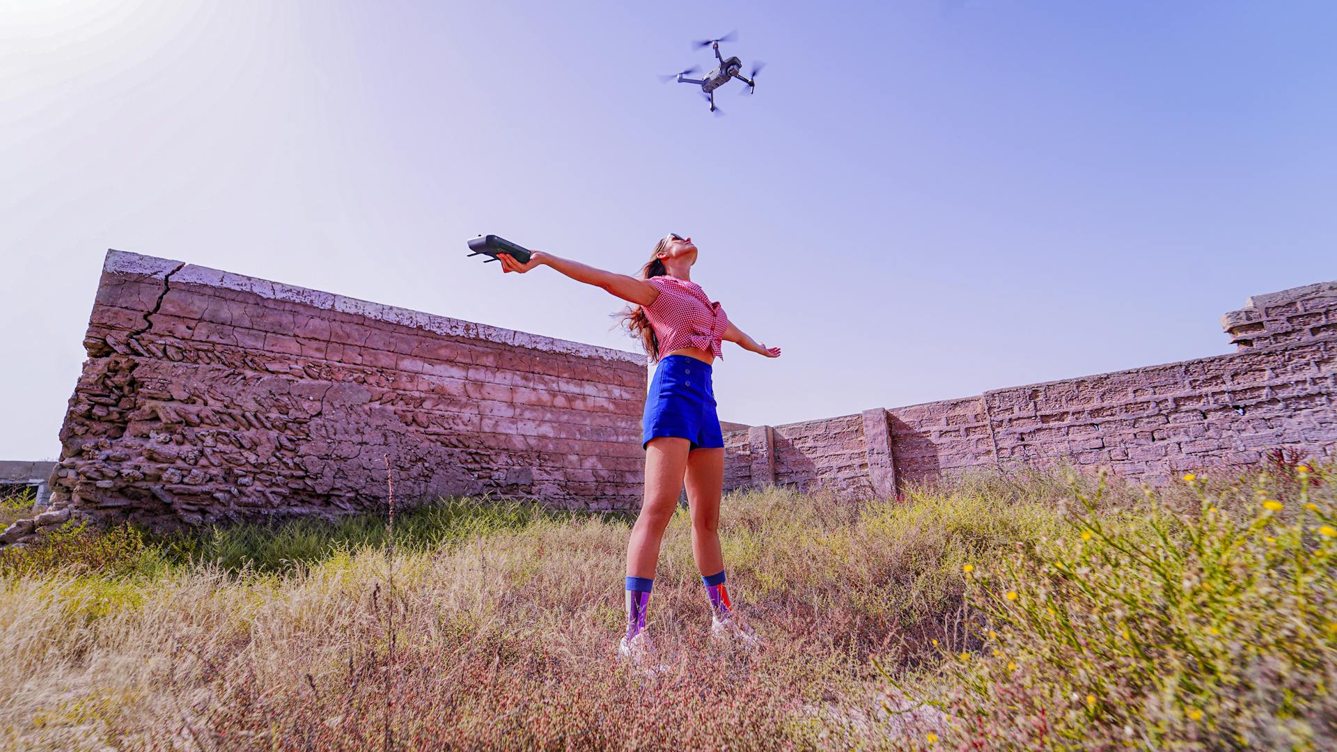
The controller features 14 channels, including 6 analog inputs and 8 digital inputs, making it versatile for various applications. This allows for a wide range of control options.
It has two joysticks, two potentiometers, two toggle switches, six buttons, and an internal measuring unit consisting of an accelerometer and a gyroscope. This provides a comprehensive set of controls for precise control.
4G Drone Mission
The 4G drone mission was a test of BVLOS control, where a drone was controlled remotely from 70 miles away. This distance was significant, but it felt like a long drive rather than an impossible feat.
An SSH connection was established from 70 miles away, and then a Python dronekit script was initiated from the command line. This setup allowed for remote control of the drone.
Frequently Asked Questions
Can I control my drone with my phone?
Yes, you can control your drone with your phone using a virtual joystick feature. This allows you to fly and navigate your drone remotely from your mobile device.
Featured Images: pexels.com
